![]()
VGA->LCD Converter Baby-Step
• Chris Liscio
![]()
• Chris Liscio
I made a very interesting discovery last night when I was about to whip that LCD panel out the window for not working after all the effort I put into the project…</p><p>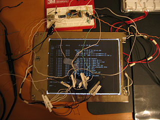 </p><p>You probably already know where the panel came from, so I won't repeat that.</p><p>The 50,000-foot view of the project is that I want to take an analog VGA signal coming out of a plain ol' VGA card, and pass it into an old TFT LCD panel via its digital interface (6-bit RGB interface for a total of 512 colours). To simplify the project, I only want to use one bit per colour (8 colours total) so I'm not messing around with so much componentry.</p><p>The first challenge was getting power to the LCD's backlight. As we may already know, there's a CCFL (cold-cathode fluorescent lamp?) backlight on pretty much every TFT LCD out there – it provides the "backbone" of the bright light that emits from your LCD. Powering one of these things is a challenge as it requires about 400V (at about 2mA), with a kickoff voltage of about 1500V. I managed to find an inverter from my local electronics store that could supply a 900V kickoff with a 400V output, and after finding just the right wall-wart to power it, that did the trick.</p><p>After seeing a constant backlight, I worked long and hard getting the panel interface "buzzed-out" (using the continuity function of a multimeter to find out which pins correspond to which loose wires). After that, I attached all the loose cables to my breadboard containing a simple amplifier/inverter circuit and hoped for something on the screen. Nothing.</p><p>In the middle of all this, I grabbed a used oscilloscope on eBay (fantastic deal) and tested my circuit out the wazoo. Needless to say, the scope said it was all working perfectly. Whatever</p><p>I was convinced that everything was shot to hell (burnt panel, or destroyed circuitry somewhere), when I decided to just check the breadboard connections versus the pins on the interface connector on the panel. Sure enough, something wasn't right.</p><p>I actually managed to label all the loose wires BACKWARDS! That's right, pin 1 was labeled 15, 2 labeled 14, and so on. At least pin 8 was okay. ;)</p><p>Anyway. It now seems to work, as you can see in the picture. I rule.
</p>